9.4 - Low-Pressure Leak Detection and Pressurization
Module: Type III Low-Pressure Appliances
Technical and regulatory verification date: August 13, 2026
Primary current authority: Current EPA Section 608 Type III test topics and current 40 CFR § 82.156 service-practice requirements
Exam-preparation focus: Classic Type III leak-test methods, pressure limits, and equipment distinctions
Course role: Teaches how a technician safely raises the pressure of a charged low-pressure chiller so inward leaks can be located, how water-box and tube leaks are checked, and why pressure limits and relief protection are especially important on low-pressure equipment
Learning Objectives
After completing this section, a student should be able to:
- Explain why a low-pressure chiller often must be temporarily pressurized before ordinary outward leak-location methods can be effective.
- State the current EPA Type III order of preference for low-pressure leak-test pressurization methods.
- Explain how controlled hot water, approved system heating/pressurization devices, and heater blankets raise refrigerant pressure without adding a noncondensable gas.
- Explain when nitrogen may be used for leak-test pressurization and why it must be introduced through a regulator and appropriate pressure protection.
- State the 10 psig Type III exam-preparation maximum leak-test pressure and explain why exceeding it is dangerous.
- Distinguish the chiller leak-test pressure limit from the separate 15 psig low-pressure recovery-vessel rupture-disc value.
- Apply the current § 82.156 restrictions on using nitrogen when pressurizing a low-pressure appliance for a qualifying non-major repair.
- Explain the correct preparation for leak checking a water box through its drain connection.
- Identify a hydrostatic tube test kit as the classic Type III method for checking heat-exchanger tubes for water-side leakage.
- Identify the shaft seal as a high-priority leak location on an open-drive compressor.
- Explain why an approved pressure limit, the manufacturer rating, and installed relief protection must all be respected during field service.
Introduction
Low-pressure chillers create a leak-detection problem that is different from the problem encountered on many Type II systems.
During normal subatmospheric operation:
Pinside < Patmosphere
so a leak can behave as:
AIR + MOISTURE
→ INTO THE CHILLER
A refrigerant detector placed outside the leak may therefore receive little or no outward refrigerant flow while the chiller remains under vacuum.
To locate such a leak, the technician can temporarily raise the refrigerant-system pressure so that:
Pinside > Patmosphere
and the leak direction becomes:
refrigerant / test gas
→ OUT through leak
The pressure increase must be controlled because low-pressure centrifugal chillers are not designed to tolerate the same service-test pressures commonly encountered on high-pressure equipment.
EPA’s current Type III test-topic page specifically expects technicians to know:
- The order of preference for pressurizing low-pressure systems for leak testing.
- The maximum leak-test pressure for low-pressure centrifugal chillers.
- Signs of leakage into low-pressure systems.
- Allowed pressurization methods for qualifying non-major repairs.
Classic Type III exam-preparation details include:
FIRST CHOICE
Controlled hot water or heater blankets
WHEN HEAT IS NOT FEASIBLE
Nitrogen can be used for leak-test pressurization
TYPE III EXAM-PREP MAXIMUM
Do not exceed 10 psig
Excessive pressure can cause the chiller’s rupture disc or another relief device to operate.
For Type III exam preparation, the separate classic value for a low-pressure recovery-vessel rupture disc is 15 psig. This is not a universal chiller relief-device rating.
Key Concepts
1. Why Pressurization Helps Find a Low-Pressure Leak
Suppose a chiller is operating below atmospheric pressure and has a small gasket leak.
Under normal conditions:
Atmosphere
→ gasket leak
→ chiller
Air enters rather than refrigerant leaving.
If the refrigerant inside the charged chiller is safely warmed, its saturation pressure rises.
When system pressure becomes slightly positive relative to atmosphere:
Chiller
→ leak opening
→ atmosphere
The leak can then be located using an appropriate refrigerant-compatible leak detector or approved leak-location method.
Exam Relationship
LOW-PRESSURE CHILLER
normally under vacuum
↓
CONTROLLED PRESSURIZATION
↓
outward leakage becomes detectable
Preferred Pressurization Methods
1. Current EPA Type III Order of Preference
Source: EPA Section 608 Test Topics
EPA currently lists the order of preference for low-pressure leak-test pressurization as:
1. HOT WATER METHOD
   or approved built-in system heating/pressurization device
followed by:
2. NITROGEN
This order matters for exam preparation.
Classic Type III exam preparation also presents these heat-based approaches:
controlled hot water
or
heater blankets
For leak-test pressurization, regulated nitrogen is the second-choice method after hot water or an approved built-in heating/pressurization device; use a heater blanket only when manufacturer-authorized.
2. Why Heat Is Preferred
Heating the refrigerant already in the chiller raises refrigerant saturation pressure without intentionally adding another gas to the refrigerant circuit.
Conceptually:
Controlled heat added
→ refrigerant temperature rises
→ refrigerant saturation pressure rises
→ chiller becomes slightly positive
→ outward leak can be located
Advantages include:
- No added nitrogen that later has to be removed.
- Less introduction of noncondensable gas.
- Uses the refrigerant’s own pressure-temperature relationship.
- Aligns with the current regulatory preference for qualifying non-major pressurization where heat is required.
The heat must be controlled.
Do not use:
- Open flame.
- Torch heating.
- Unapproved localized overheating.
- Any method prohibited by the chiller manufacturer.
Controlled Hot Water
1. Basic Method
Controlled warm/hot water can be circulated through the chiller water side to raise refrigerant temperature and pressure.
A simplified sequence is:
Warm water circulated through appropriate chiller heat exchanger
↓
Tube wall transfers heat to refrigerant
↓
Refrigerant temperature rises
↓
Refrigerant pressure rises
↓
System reaches controlled positive pressure
↓
Technician searches for outward leaks
2. Why This Method Is Effective
The large shell-and-tube heat exchangers provide substantial heat-transfer area.
The water side can therefore warm the refrigerant relatively uniformly compared with heating one small metal location intensely.
3. Control Requirements
The technician must monitor:
- Chiller refrigerant pressure.
- Water temperature.
- Applicable manufacturer limits.
- Relief-device condition.
- Which water circuit is being heated or circulated.
The objective is not to heat the chiller as much as possible.
The objective is:
raise pressure only enough for the approved service purpose
while remaining within the permitted pressure limit.
Heater Blankets and Built-In Pressurization Devices
1. Heater Blankets
An approved heater blanket is one controlled heat-based option for warming a charged low-pressure appliance during leak checking.
A properly applied heater blanket provides controlled external heating without introducing nitrogen.
The general idea is:
Approved heater blanket
→ controlled heat input
→ refrigerant pressure rises
Use only equipment and locations approved by the chiller manufacturer.
Do not improvise an uncontrolled electric heater directly against vulnerable wiring, insulation, gaskets, relief devices, or other components.
2. Built-In Heating / Pressurization Systems
EPA’s current Type III test topics also mention an approved built-in system heating/pressurization device, historically exemplified by systems such as Prevac.
For examination purposes, understand the category:
BUILT-IN SYSTEM HEATING / PRESSURIZATION DEVICE
→ preferred before nitrogen
The exact equipment design and operating procedure are manufacturer-specific.
Nitrogen Pressurization
1. Nitrogen as the Secondary Leak-Test Method
EPA’s current Type III test-topic outline places nitrogen second after hot water or approved built-in heating/pressurization.
The current Type III preference can be summarized as:
Use hot water or an approved built-in heating/pressurization device first
→ use regulated nitrogen as the second-choice leak-test method
This statement concerns leak-test pressurization.
It must not be interpreted as permission to use nitrogen in every low-pressure service situation.
2. Nitrogen Must Be Regulated
A commercial nitrogen cylinder contains pressure far above the allowable pressure of a low-pressure chiller.
Therefore the safe connection concept is:
NITROGEN CYLINDER
→ PRESSURE REGULATOR
→ CONTROLLED LOW-PRESSURE SUPPLY
→ CHILLER
Use:
- A suitable regulator.
- Appropriate gauges.
- Appropriate downstream overpressure protection.
- Hoses and fittings rated for the service.
- Manufacturer-approved connection point.
Never connect a high-pressure nitrogen cylinder directly to the chiller without a regulator.
3. Never Use Oxygen or Compressed Air
General Section 608 safety principles remain in effect:
NO OXYGEN
NO COMPRESSED AIR
for refrigerant-system pressure testing.
Oxygen can react dangerously with refrigeration oil and other materials.
Compressed air adds moisture and oxygen and is not the approved Type III pressure-test gas.
Maximum Leak-Test Pressure
1. Type III Exam-Preparation Value
For Type III exam preparation, use this limit:
DO NOT EXCEED 10 psig
when pressurizing a charged low-pressure centrifugal chiller for leak checking.
Excessive pressurization can cause the chiller’s rupture disc or another pressure-relief device to operate.
EPA’s current Type III test-topic page continues to list:
Maximum leak test pressure for low-pressure centrifugal chillers
as an examination topic, although the current public topic page does not print the numerical answer.
For this course and Type III exam preparation, use:
10 psig MAXIMUM LEAK-TEST PRESSURE
This value is an upper limit, not a required target pressure.
High-Priority Exam Rule
LOW-PRESSURE CENTRIFUGAL CHILLER
LEAK TEST
→ DO NOT EXCEED 10 psig
2. 10 psig Is a Maximum, Not a Target
Do not interpret the exam value as:
Every leak test must be performed at exactly 10 psig
The safer principle is:
Use only the pressure needed for the approved test
AND
never exceed the applicable limit
A specific manufacturer may require a lower test pressure or a particular controlled procedure.
The manufacturer’s allowable pressure must always be respected in field work.
3. Why Excessive Pressure Is Dangerous
Low-pressure chillers can contain very large shells and heat exchangers designed around relatively low refrigerant-side pressures.
Excessive pressurization can:
- Rupture a relief disc.
- Operate another relief device.
- Stress vessel shells.
- Stress gaskets and flanges.
- Damage service components.
- Release refrigerant.
- Create a personnel hazard.
Therefore:
MORE PRESSURE
≠
BETTER LEAK TEST
Rupture-Disc Pressure: Keep the Exam Values Separate
1. Chiller Leak-Test Warning
The classic Type III exam-preparation limit is:
Do not exceed 10 psig when pressurizing the chiller for leak checking.
Excessive pressurization can cause the disc or another relief device to operate.
This is the number relevant to low-pressure chiller leak-test pressurization.
2. Separate Recovery-Vessel Value
A separate classic recovery-equipment value is:
Low-pressure RECOVERY VESSEL rupture disc
→ relieves at 15 psig
For Type III exam preparation, the classic high-pressure cutout value for recovery equipment used with low-pressure appliances is 10 psig.
These recovery-equipment values belong primarily in Section 9.5, but they are introduced here to prevent a common mistake.
Do Not Merge These Statements
Do not conclude:
Every low-pressure chiller has a rupture disc rated exactly 15 psig
In this classic exam-preparation context, the 15 psig value applies specifically to a low-pressure recovery vessel.
Actual chiller pressure-relief-device ratings and arrangements are equipment-specific and must follow:
- Manufacturer documentation.
- Equipment listing/design.
- Applicable code.
- Installed relief-device markings.
Memory Table
| Exam / Service Item | Value or Rule |
|---|---|
| Low-pressure chiller leak-test pressurization | Do not exceed 10 psig |
| Type III pressure warning | Excessive pressure can cause the chiller’s rupture disc or another relief device to operate |
| Low-pressure recovery-unit high-pressure cutout | 10 psig — developed further in 9.5 |
| Low-pressure recovery-vessel rupture disc | 15 psig — developed further in 9.5 |
| Actual installed chiller relief-device rating | Verify manufacturer / device / code; do not assume 15 psig universally |
Nitrogen and the Current Non-Major Repair Rule
The leak-test procedure above must be distinguished from the current federal rule for opening a low-pressure appliance for a qualifying non-major repair.
Source: 40 CFR § 82.156(a)(1)(ii)
When all conditions of the non-major exception are satisfied and evacuation of the appliance to the atmosphere is not to be performed after the repair, a low-pressure appliance must be:
PRESSURIZED TO NO HIGHER THAN 0 psig
before it is opened
The regulation then controls how the pressure can be raised.
1. Refrigerant Boiling Point at or Below 85°F
For a low-pressure appliance using a refrigerant whose boiling point is:
≤ 85°F at 29.9 in. Hg atmospheric pressure
methods such as nitrogen that require subsequent purging:
MUST NOT BE USED
for this non-major opening procedure.
2. Refrigerant Boiling Point Above 85°F
For a low-pressure appliance using refrigerant whose boiling point is:
> 85°F at 29.9 in. Hg atmospheric pressure
the technician must:
use HEAT to raise internal pressure as much as possible
and may then use nitrogen only to raise the pressure:
from the heat-attainable level
→ to atmospheric pressure
3. EPA’s Current Service-Practice Summary
EPA’s current service-practice page summarizes the common practical distinction by stating that methods requiring subsequent purging, such as nitrogen, cannot be used for the low-pressure non-major opening procedure except with appliances containing R-113.
The regulation itself is written using the refrigerant boiling-point criterion above.
Exam / Field Distinction
LEAK TESTING
→ EPA test topics: heat preferred, nitrogen second
is not the same as:
PRESSURIZING TO OPEN FOR QUALIFYING NON-MAJOR REPAIR
→ §82.156 restrictions apply
This distinction is important.
Leak-Location Methods After Safe Pressurization
Once a charged low-pressure chiller has been safely raised to an approved positive pressure, the technician can inspect likely leak locations using a refrigerant-compatible method.
Potential methods can include:
- Compatible electronic refrigerant detector.
- Approved bubble solution at accessible joints where appropriate.
- Manufacturer-specified leak detection procedure.
The focus in Type III is not merely which detector is used; it is how the low-pressure system is safely brought to a condition where an outward leak can be detected.
Likely refrigerant-side leak locations include:
- Flange gaskets.
- Service fittings.
- Valve stems.
- Charging connections.
- Purge-system connections.
- Compressor shaft seal on open-drive machines.
- Other manufacturer-identified seals and joints.
Open-Drive Compressor Shaft Seal
1. Why It Is a High-Priority Leak Location
An open-drive compressor has a rotating shaft that passes through the compressor housing to an external motor or drive.
A seal is required where the rotating shaft penetrates the refrigerant-containing housing.
Because that seal must accommodate motion:
OPEN-DRIVE COMPRESSOR
→ SHAFT PENETRATION
→ SHAFT SEAL
→ IMPORTANT LEAK LOCATION
In the classic Type III exam model, the shaft seal is a likely leak location on an open-drive compressor.
2. Leak Direction Can Change
When the compressor/seal region is subatmospheric:
air can leak IN
When the region is intentionally or naturally at positive pressure:
refrigerant can leak OUT
This makes the shaft seal particularly important during controlled positive-pressure leak testing.
3. Do Not Generalize to Every Centrifugal Chiller
Not every centrifugal chiller is open drive.
Some are:
- Hermetic.
- Semi-hermetic.
- Direct-drive.
- Oil-free magnetic-bearing designs.
Therefore:
OPEN-DRIVE MACHINE
→ check shaft seal carefully
but:
EVERY centrifugal chiller
→ has external shaft seal
is incorrect.
Water-Box Leak Testing
1. What a Water Box Is
Section 9.2 established that water boxes belong to the water side of the shell-and-tube heat exchanger.
They direct chilled water or condenser water through the tubes.
A water box is not normally filled with refrigerant.
2. Classic Type III Water-Box Test Procedure
For exam preparation, use this specific procedure:
Before leak testing a WATER BOX
→ remove the water
→ place refrigerant-detector probe through the drain valve
Why remove the water first?
If water remains in the water box, it can interfere with access and with detecting refrigerant that may be leaking through a tube or tube-to-tube-sheet boundary into the water-side space.
Exam Memory Rule
WATER-BOX LEAK TEST
→ REMOVE WATER FIRST
→ PROBE THROUGH DRAIN VALVE
Follow the actual chiller manufacturer’s isolation, drainage, confined-space, and water-side service procedure in field work.
Tube-Leak Testing
1. Why Tube Leaks Matter
A tube leak creates communication between:
WATER SIDE
and:
REFRIGERANT SIDE
When water-side pressure exceeds refrigerant-side pressure:
water can enter refrigerant circuit
This is why Section 9.3 connected excessive purge moisture with possible tube leakage.
2. Classic Type III Exam Method
The classic Type III tube-leak test method is:
To leak test a tube
→ use a HYDROSTATIC TUBE TEST KIT
A hydrostatic tube test evaluates individual heat-exchanger tubes or tube circuits using controlled water pressure and appropriate test equipment.
High-Priority Distinction
WATER BOX
→ drain water before refrigerant detector probe through drain valve
TUBE
→ hydrostatic tube test kit
Do not confuse the two methods.
3. Actual Manufacturer Procedures Control
Modern chiller tube testing can also involve manufacturer-approved:
- Tube plugs.
- Pressure/vacuum methods.
- Eddy-current testing for tube condition.
- Other specialized inspection methods.
For EPA Type III exam preparation, retain the classic relationship:
HYDROSTATIC TUBE TEST KIT
→ tube leak testing
Avoiding Excessive Pressure
1. Use Pressure as a Controlled Diagnostic Tool
A leak test only requires enough pressure differential to make the leak detectable.
The technician should not increase pressure merely because a leak has not yet been found.
A correct reasoning sequence is:
Verify manufacturer-approved test method
↓
Verify relief protection
↓
Apply preferred heating method when feasible
↓
Monitor pressure continuously
↓
Use only necessary positive pressure
↓
Never exceed the applicable maximum
↓
Locate leak
↓
Remove test condition safely
2. Why a Pressure Regulator Alone Is Not Enough
A regulator can fail, be misadjusted, or supply pressure higher than intended.
When nitrogen is used, good service practice includes appropriate downstream overpressure protection in addition to the regulator.
This principle was established in Section 6.5.
3. Do Not Defeat the Chiller’s Relief Protection
Never:
- Cap a required relief path.
- Plug a rupture-disc outlet.
- Isolate the refrigerant vessel from required relief protection.
- Replace a rupture disc with an ordinary valve.
- Raise pressure to intentionally test the relief device.
4. Stop if Pressure Rises Unexpectedly
If pressure increases faster or higher than expected:
STOP ADDING HEAT / NITROGEN
→ isolate pressure source
→ determine cause
Possible causes can include:
- Excessive heat input.
- Regulator error.
- Valve arrangement error.
- Unexpected system isolation.
- Incorrect pressure indication.
- Local trapped volume.
Leak-Test Decision Sequence
Use this Type III decision process:
STEP 1
Is the charged chiller below atmospheric pressure?
If yes, an outward leak may be difficult to locate.
STEP 2
Can controlled hot water or an approved heating/
pressurization system be used?
If yes:
PREFER HEAT
If no and the service procedure permits:
USE REGULATED NITROGEN
Then:
STEP 3
Monitor pressure continuously
→ Type III exam-prep maximum 10 psig
→ manufacturer lower limit controls if applicable
Then:
STEP 4
Check likely leak locations
including:
- Gaskets.
- Fittings.
- Valves.
- Purge connections.
- Open-drive shaft seal.
For water-side diagnosis:
Water box → drain first → detector through drain valve
Tube → hydrostatic tube test kit
Technical and Regulatory Details
1. Leak-Test Pressurization Versus Non-Major Opening
| Situation | Main Pressure Concept | Nitrogen Treatment |
|---|---|---|
| Charged low-pressure chiller leak test | Create controlled positive pressure; project Type III exam-prep maximum 10 psig | EPA test topics place nitrogen after hot water / approved heating |
| Qualifying non-major repair before opening | Current §82.156: pressurize to no higher than 0 psig | Restricted by refrigerant boiling point; heat required/preferred by regulation |
| Recovery operation | Separate recovery-equipment pressure controls | 10-psig recovery-unit cutout and 15-psig recovery-vessel rupture disc are classic Type III recovery values; see 9.5 |
This table prevents three different pressure concepts from being confused.
2. Type III Pressurization Number Map
10 psig
→ classic maximum low-pressure CHILLER LEAK-TEST pressure
0 psig
→ current qualifying NON-MAJOR opening pressure limit
10 psig
→ classic low-pressure RECOVERY UNIT high-pressure cutout
15 psig
→ classic low-pressure RECOVERY VESSEL rupture-disc relief value
The repeated 10 psig appears in two different contexts. Read the question carefully.
3. Current Versus Legacy Source Control
The current EPA public Type III test-topic page explicitly lists:
- Hot water / built-in heating first.
- Nitrogen second.
- Maximum leak-test pressure.
- Low-pressure signs of leakage.
- Pressurization methods for non-major repair.
In the classic Type III exam-preparation model, the maximum leak-test pressure is 10 psig, with related service details covering water boxes, tube testing, and shaft seals.
The current regulation §82.156 controls the legal non-major opening procedure and nitrogen restrictions.
Field service must also comply with the actual chiller manufacturer’s pressure limits and relief-device design.
Important Terms
Controlled Hot-Water Pressurization
Controlled hot-water pressurization uses warm/hot water circulated through an appropriate chiller heat exchanger to raise refrigerant temperature and pressure in a controlled manner without intentionally introducing a noncondensable gas.
Heater Blanket
A heater blanket is an approved external heating device used to warm part of the chiller/refrigerant system in a controlled manner. Use it for leak-test pressurization only where and as authorized by the chiller manufacturer.
Hydrostatic Tube Test Kit
A hydrostatic tube test kit is equipment used to test heat-exchanger tubes for leakage using controlled liquid pressure. It is a classic Type III exam answer for tube-leak testing.
Leak-Test Pressure
Leak-test pressure is the controlled pressure established to make leakage detectable. For Type III examination preparation, treat 10 psig as the maximum—not the required target—for a low-pressure centrifugal-chiller leak test.
Open-Drive Shaft Seal
An open-drive shaft seal seals the location where a rotating compressor shaft passes through the refrigerant-containing compressor housing. It is a classic leak-prone location on open-drive low-pressure systems.
Rupture Disc
A rupture disc is a non-reclosing pressure-relief device designed to open at its rated condition to protect equipment against excessive pressure. Do not assume one universal rating for every chiller.
Water Box
A water box is the water-side chamber at the end of a shell-and-tube heat exchanger. The classic Type III water-box leak test requires draining the water before inserting a refrigerant-detector probe through the drain connection.
Figures and Diagrams
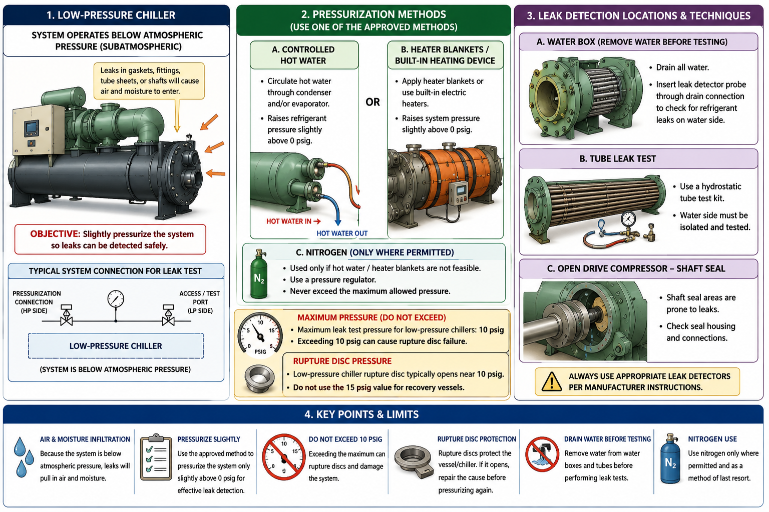
Figure 9.4.1 - Controlled Type III leak-test pressurization and the principal low-pressure leak-location checks.
AI-generated instructional figure: It may contain visual inaccuracies. Use the accompanying lesson text and cited authoritative sources to verify technical and regulatory details.
EPA 608 Exam Focus
What Students Must Remember
- Low-pressure chillers can draw air and moisture inward while operating below atmospheric pressure.
- To locate an outward refrigerant leak, the charged appliance can be carefully pressurized using approved methods.
- EPA’s current Type III order of preference is:
- Hot water / approved system heating or pressurization device.
- Nitrogen.
- An approved heater blanket can provide controlled heat-based pressurization when the manufacturer authorizes its use.
- For this project’s Type III exam preparation, the low-pressure chiller leak-test pressure must not exceed 10 psig.
10 psigis a maximum, not a target for every test.- Excessive pressure can operate a rupture disc or another relief device and can damage equipment.
- The classic 15 psig rupture-disc value belongs to a low-pressure recovery vessel, not automatically to every chiller.
- When nitrogen is used, it must be regulated and pressure controlled.
- Never use oxygen or compressed air for refrigerant-system pressure testing.
- For a current qualifying non-major opening, §82.156 requires the low-pressure appliance to be pressurized to no higher than 0 psig before opening.
- Nitrogen use for that non-major opening procedure is restricted according to refrigerant boiling point; it is not the same rule as leak-test pressurization.
- For a water-box leak test, remove the water first before placing the detector probe through the drain valve.
- For tube leak testing, the classic Type III answer is a hydrostatic tube test kit.
- On an open-drive compressor, the shaft seal is a high-priority leak location.
High-Priority Relationships
LOW-PRESSURE LEAK TEST
→ HEAT FIRST
→ NITROGEN SECOND where permitted
MAX LEAK-TEST PRESSURE
→ 10 psig
QUALIFYING NON-MAJOR OPENING
→ no higher than 0 psig
WATER BOX
→ remove water
→ probe through drain valve
TUBE
→ hydrostatic tube test kit
OPEN DRIVE
→ check shaft seal
Typical Exam Question Patterns
Students may be asked to:
- Identify the preferred way to pressurize a charged low-pressure chiller for leak checking.
- Select nitrogen when approved heating is not feasible.
- Identify 10 psig as the maximum Type III leak-test pressure.
- Explain why excessive pressurization can damage or operate the rupture-disc protection.
- Distinguish the 10-psig chiller leak-test value from the separate recovery-vessel value.
- Identify the current non-major opening pressure as 0 psig.
- Determine when nitrogen is restricted for a non-major opening.
- Identify the correct water-box leak-test preparation.
- Identify the hydrostatic tube test kit as the tube-leak test method.
- Identify the shaft seal as a likely leak point on an open-drive compressor.
High-Risk Words
Pay particular attention to:
- Preferred
- Hot water
- Heater blanket
- Nitrogen
- Maximum
- 10 psig
- Rupture disc
- Recovery vessel
- 15 psig
- 0 psig
- Water box
- Drain valve
- Hydrostatic
- Shaft seal
- Open drive
Common Mistakes and Confusing Points
Mistake 1: Trying to Find Every Low-Pressure Leak While the Chiller Is Deep Under Vacuum
A leak can be drawing air inward.
Controlled positive pressure may be needed to produce an outward leak that can be detected.
Mistake 2: Choosing Nitrogen Before Heat
For Type III exam preparation, the current EPA order is:
heat / approved heating first
→ nitrogen second
Mistake 3: Using an Open Flame to Raise Pressure
Use controlled approved heating only.
Do not use a torch or flame on the chiller.
Mistake 4: Connecting Nitrogen Without a Regulator
A nitrogen cylinder can contain thousands of psi.
A low-pressure chiller must never be connected directly to uncontrolled cylinder pressure.
Mistake 5: Assuming 10 psig Is the Required Test Pressure
It is the Type III exam-preparation maximum.
The actual test can require less pressure.
Mistake 6: Pressurizing Above 10 psig Because a Leak Has Not Been Found
More pressure increases risk and does not replace proper leak-location technique.
Mistake 7: Assuming the Chiller Rupture Disc Is Universally 15 psig
The classic 15 psig exam value applies to a low-pressure recovery vessel; it is not a universal chiller relief-device rating.
Actual chiller relief-device ratings are equipment-specific.
Mistake 8: Confusing Leak-Test Pressurization With Non-Major Opening Pressurization
Leak test:
controlled positive pressure, exam maximum 10 psig
Qualifying non-major opening:
no higher than 0 psig under current §82.156
These are different operations.
Mistake 9: Assuming Nitrogen Is Always Allowed for the Non-Major Opening Procedure
Current §82.156 restricts methods requiring subsequent purging according to refrigerant boiling point.
Mistake 10: Leaving Water in the Water Box During the Classic Detector-Probe Test
Remove the water first.
Mistake 11: Using the Water-Box Detector Procedure as the Tube Test
For a tube, the classic Type III answer is:
hydrostatic tube test kit
Mistake 12: Checking a Shaft Seal on a Hermetic Compressor That Has No External Shaft Penetration
The shaft-seal leak clue specifically applies to open-drive compressors.
Mistake 13: Defeating the Rupture Disc During a Pressure Test
Relief protection must remain effective.
Never block required relief merely to hold test pressure.
Concept-Check Questions
Question 9.4-1
What is the preferred Type III method for raising the pressure of a charged low-pressure chiller for leak testing?
A. Controlled hot water or an approved heating/pressurization method
B. Oxygen directly from a cylinder
C. Compressed shop air
D. Immediately raise the system to the rupture-disc pressure
Question 9.4-2
If controlled hot water or an approved heating method is not feasible for a Type III leak test, which pressurization method is next in the current EPA test-topic order?
A. Oxygen
B. Acetylene
C. Regulated nitrogen where permitted
D. Compressed air
Question 9.4-3
For Type III exam preparation, what is the maximum pressure to which a low-pressure centrifugal chiller should be pressurized for leak testing?
A. 0 psig
B. 5 psig
C. 10 psig
D. 15 psig
Question 9.4-4
Which statement correctly distinguishes two commonly confused Type III pressure values?
A. Every low-pressure chiller rupture disc is universally 15 psig, and the leak-test maximum is also 15 psig.
B. The chiller leak-test exam-preparation maximum is 10 psig, while the 15-psig rupture-disc value specifically refers to a low-pressure recovery vessel.
C. The chiller leak-test maximum is 150 psig, while the recovery vessel is 10 psig.
D. The 10- and 15-psig values both refer only to chilled-water pressure.
Question 9.4-5
For the classic Type III water-box leak test using a refrigerant detector, what should be done before placing the probe through the drain valve?
A. Fill the water box completely with water.
B. Remove the water from the water box.
C. Pressurize the water box to 150 psig with oxygen.
D. Open the rupture disc.
Question 9.4-6
In the classic Type III exam method, what equipment is used for leak testing an individual chiller tube?
A. Hydrostatic tube test kit
B. Vacuum cleaner
C. Recovery-cylinder scale
D. Crankcase heater
Question 9.4-7
Which location deserves particular leak attention on a low-pressure system using an open-drive compressor?
A. Shaft seal
B. Hermetic motor winding inside a welded shell
C. Cooling-tower fan blade
D. Chilled-water expansion tank only
Question 9.4-8
A technician is preparing to open a low-pressure appliance for a qualifying non-major repair under current §82.156. Which statement is correct?
A. The 10-psig leak-test maximum means the appliance may be opened at 10 psig.
B. The appliance must be pressurized to no higher than 0 psig before opening, and nitrogen use is restricted by the rule’s refrigerant boiling-point conditions.
C. The appliance must always be opened while under deep vacuum.
D. Nitrogen must always be used regardless of refrigerant.
Answers and detailed explanations will be provided in
9.15 - Answers and Explanations.md.
Section Summary
Low-pressure chiller leak detection often requires temporarily changing the direction of leakage.
Under normal vacuum operation:
Pinside < Patmosphere
→ AIR + MOISTURE IN
For leak location:
controlled pressurization
→ slight positive pressure
→ leak can move OUTWARD
The current EPA Type III test-topic preference is:
1. CONTROLLED HOT WATER / APPROVED HEATING-PRESSURIZATION
2. NITROGEN
An approved heater blanket is also a controlled heat-based option when authorized by the manufacturer.
For exam preparation:
LOW-PRESSURE CHILLER LEAK TEST
→ DO NOT EXCEED 10 psig
The separate classic recovery-vessel value is:
15 psig
→ LOW-PRESSURE RECOVERY-VESSEL rupture disc
Do not misapply this value as a universal chiller rupture-disc rating.
For a qualifying non-major opening, the current federal requirement is different:
LOW-PRESSURE APPLIANCE
→ pressurize to no higher than 0 psig before opening
with nitrogen restricted according to the refrigerant boiling-point conditions in §82.156.
Classic Type III leak-location reminders are:
WATER BOX
→ drain water first
→ detector through drain valve
TUBE
→ hydrostatic tube test kit
OPEN-DRIVE COMPRESSOR
→ inspect shaft seal
The next section applies Type III pressure and component knowledge to removal of the refrigerant charge:
Section 9.5 - Type III Recovery Sequence.
References
Current EPA and Regulatory Sources
-
U.S. Environmental Protection Agency, Section 608 Test Topics, Type III leak-detection, pressurization, recovery, and non-major repair topics, verified August 13, 2026.
-
U.S. Environmental Protection Agency, Stationary Refrigeration Service Practice Requirements, current non-major low-pressure service-practice summary, verified August 13, 2026.
-
Electronic Code of Federal Regulations, 40 CFR § 82.156 - Proper Evacuation of Refrigerant From Appliances, current low-pressure non-major pressurization and nitrogen restrictions, verified August 13, 2026.
Project Teaching and Exam-Preparation Sources
-
International Training Institute / ESCO-style project copy, EPA Section 608 Study Guide, Type III Leak Detection and Recovery Techniques. This source supports the classic exam-preparation relationships: controlled hot water or heater blankets first; nitrogen if heating is not feasible; do not exceed 10 psig during low-pressure chiller leak testing; excessive pressure can cause rupture-disc failure; drain a water box before probing through its drain valve; use a hydrostatic tube test kit for tubes; inspect open-drive shaft seals; low-pressure recovery-unit cutout at 10 psig; low-pressure recovery-vessel rupture disc at 15 psig.
-
Rex Miller and Mark R. Miller, HVAC Licensing Study Guide, 3rd ed., general nitrogen-cylinder regulation, pressure-test safety, relief protection, refrigerant leak testing, and compressed-gas handling principles. General high-pressure test values from this reference are not applied to low-pressure centrifugal chillers.